Basic Wiring Of Fuselage, Instruments and Power Source
For Analog Instrument Panel


On this electrical wiring page, we hope to make wiring your Challenger a little easier by understanding what items are wired to where. We will be covering wiring of most items you will normally find on the typical Challenger, some specialty items as well as wiring from a few different Challenger builds.

We will start at the instrument panel and work our way back to the engine firewall, covering as many items as possible that need to be wired.


The Analog Instrument Panel

Front View
Click to Enlarge
Photo Courtesy of:
Mike Harrison
         

On each row from left to right are.
ROW 1: 1. Master Power Switch, 2. Air Speed Indicator (ASI), 3. Altimeter (ALT), 4. Ignition Switch
ROW 2: 5. Tachometer, 6. DUAL CHT Gauge, 7. Ball Yaw indicator/Liquid Compass, 8. DUAL EGT Gauge, 9. Fuel Gauge


Each Component

First of all, the following instruments have no wiring needed: Air Speed Indicator (ASI), Altimeter (ALT), Liquid Compass and one not mentioned, the Ball Yaw Control Indicator, located just below the compass on the front of the panel. To help you follow along with the wiring, we recommend you download the following electrical schematic.


Master Power Switch:
This switch is where "ALL" of the power is supplied to your instruments, starter switch and some items in the rear of the plane. The Master Power Switch is a lighted switch and has three wiring poles. The top pole is the +12v input, the center pole is for the light in the switch and is wired in series with the output pole on the bottom. The +12v power input pole is wired directly to the small pole on the left side of the starter solenoid, which should be mounted in the rear of the plane. The light/output poles are wired directly to the +12v power bus under the instrument panel to be distributed to most items in the plane. (See +12v Power Bus below)


Click to Enlarge
         

DUAL CHT & EGT Gauges
There are four (4) pole connections of the rear of the CHT & EGT gauges. Looking at the gauges from the rear, the right two poles are for CHT/EGT #1 and the left pole connectors are for CHT/EGT #2 on each respective gauge. The gauges are wired to the firewall disconnects via the 8 AWG shielded wire cable for the CHT/EGT probes on the engine. (See Schematic) This cable should be run on the opposite side of the airframe then the power cables to reduce static interference.

CHT or EGT Gauge Wiring: Pin # 1 Front cylinder probe white wire. Pin # 8 Front cylinder probe black wire. Pin # 4 rear cylinder probe white wire. Pin # 5 rear cylinder probe black wire.


Click to Enlarge


Tachometer
The Tachometer gauge is wired to the engine "Gray Wire" via the engine 8 AWG shielded wire cable from the gauge "SIGNAL, Pin # 2" input pole with the "GND, Pin # 5" pole wired to the under panel ground bus.(See Schematic)

Gauge Wiring: Pin # 2 to engine gray tach signal wire. Pin # 5 to airframe ground.
         
Click to Enlarge


Ignition Switch:
The ignition switch starts your engine "IF" you installed the GPL Starter on the engine. Otherwise, you need to turn the key to "Both" and pull start your engine.

The connections on the back are numbered on the fact sheet to the right and wires as follows. Use an 8 wire/18 AWG, shielded cable to run from the instrument panel to the engine firewall.
1. To the right mag., wired to Black/Yellow wire #1 from the engine. NOTE: The jumper "IS NOT" used.
2. To the left mag., wired to Black/Yellow wire #2 from the engine.
3. Power, wired to the +12v Power Bus under instrument panel.
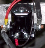
4. Start, wired directly to the small pole on the left side of the starter solenoid, same as the Master Power Switch.
5. Ground, run a "green" wire to the "brown" engine block wire.
       As the "BO" terminal is not used and was touching the lower gauge, it was removed from the switch.
The second ignition switch is for a pull start engine, no GPL starter.

         
W/Start & Pwr. Terminal
Click to Enlarge

W/O Start & Pwr. Terminals
Click to Enlarge

Click to Enlarge


On/Off Instrument Switches:
This is a set of 4 individual non-lighted, 2 pole on/off push button switches. From the top:
1. Intercom: Wired from the +12v power bus to the fuse panel, 5A fuse, to the top pole on the switch. The bottom pole is wired directly to the hot lead of the intercom unit.
2. Transponder: Most planes will not have this $1,200.00 instrument. But if you do, it is wired from the +12v power bus to the fuse panel, 5A fuse, to the top pole on the switch. The bottom pole is wired directly to the hot lead of the transponder.
3. Facet Fuel Pump: The Facet Fuel Pump is normally located in the rear of the plane, near the engine firewall. Wired from the +12v power bus to the fuse panel, 5A fuse, to the top pole on the switch. The bottom pole is wired directly to the the hot lead of the Facet pump.
4. Strobe Lights Control Box: Most strobe light controllers have their own internal fuse. In this case, the switch is wired from the +12v power bus directly to the top pole on the switch. The bottom pole is wired directly to the hot lead of the strobe controller.
5. Fuel Gauge: The capacitance fuel sender is located on the fuel tank in the rear of the fuselage. Wired from the +12v power bus to the fuse panel, 5A fuse, to the red wire on the sender unit. The yellow wire on the sender is the output signal wire which is wired to the "SIG" pole on the rear of the fuel gauge. The black wire on the sending unit is wired to ground as well as the gauge being wired to ground.

NOTE: Many flight instructors who train new pilots from the rear seat prefer having the "Facet Pump" on/off switch located on the front door frame angled cross brace. This way, should the engine bog down for any reason, it is much easier and less stressful on the new pilot if the instructor can reach this switch from the rear seat.


Under Instrument Panel Accessory Staging

Click to Enlarge
         

It may be best at this point to describe the "Under Instrument Panel Accessory Staging". Here are two different builds with the same idea to mount accessories under the instrument panel. One build used square aluminum bracing and the other build used the stock 1/2 inch aluminum tubing used in many places on the airframe. Placing the two braces about 5-1/2 inches apart will give you a perfect place to mount accessories, like a "Hot Box", Strobe Control Box", Fuel Panel and Power Bus' or in the uncommon case below, to mount an encoder box for a transponder. If you use "aluminum rivets" to attach these braces to the airframe, these braces will make an excellent ground source.

         
Click to Enlarge


(Components Continued)

Transponder Encoder
         

Transponder:
This instrument sends off a signal via an antenna mounted on the plane to control towers and major airplanes like commercial and Air Force planes to tell them of your position horizontally. When an encoder is wired to the transponder, the signal also tells them what altitude you are flying at. A pre-wired wiring harness is available to connect the transponder to the encoder (DB25 to DB15), which is highly recommended. Otherwise, the stock harness must be wired to a DB15 plug by the new owner. There are 6 loose lead wires from this harness, 4 we would not use in a Challenger, so just curl them up and tie wrap them together. This leaves an additional two loose wires, a red "HOT" lead and a black, ground. The red lead is wired to the bottom of the on/off bush button, described above. The black is wired directly to the ground bus under the instrument panel. There is also a coaxial cable connector to connect the supplied coaxial cable to a supplied 3" antenna. The coaxial cable is longer than necessary, so you will have to shorten it, affix the coaxial connector to the end and attach it to the antenna in the location you have chosen. (Recommended location of antenna: just in front of the main landing gear on the bottom of the plane. A ground plate must be installed to mount the antenna.)

         
Transponder


Click "Rear of Gauge" to Enlarge
         

Fuel Gauge with Capacitance Sender
If using a capacitance gauge sender, there are three wires on the sender unit. The yellow wire is the capacitance gauge signal wire which is wired to the fuel gauge on the instrument panel. The red wire is the +12v power lead which is wired to the fused ON/OFF switch on the instrument panel. The black wire from the capacitance gauge is wired to ground.

Gauge Wiring: Pin # 4 goes to Fuel sender yellow signal wire and pin # 5 goes to airframe ground.
         
Capacitance Gauge Sender


Front
 
Back
         

Emergency Locator Transmitter (ELT):
This is a battery operated, stand alone circuit not needing to be wired into the planes electrical system. However, the Test/Activate/Override switch is mounted on the instrument panel for emergencies in the event you have an accident and the ELT did not activate automatically. Can also be used to test for proper operation. The ELT, dash mounted, push button switch is connected to the ELT unit in the back of the plane via a supplied telephone cord with RJ-11 connectors at both ends. The only other wire is a coaxial antenna cable from the ELT unit to the antenna, usually mounted in the center gap cover.

         
Click to Enlarge


Click to Enlarge
         

Fuse Panel & Power Bus Plate:
An automotive 4 fuse panel was used for the 3, 5 amp fuses in the system with one empty and pre-wired spot in case of an accessory being added later to the system. (Top, Left) Below are two power bus', one for +12v power bus (top) and one for a ground bus (Bottom). The ground bus is attached to the frame. To the right side is a legend of the fuse box and +12v power bus connections. This panel is an inexpensive alternative to buying a "Hot Box". Total Cost: Abt. $12.00


Double Dual Magnum Controller Box:
This one is very simple in its wiring. Wire the red (hot lead) to the +12v power bus and the black wire (ground) to the ground bus. The strobe lights need to be attached to the wing tips in this case, with the wiring cables run inside the front wing spars to the fuselage. Normally, the cables will be fed down thru the front down tubes coming out below the instrument panel, near the rudder pedals and back up to the controller box. You will then shorten the cable by removing the excess wire and connecting the three pin plugs to the cables. The plugs will plug into the control box on the opposite side from the power leads.

         
Click to Enlarge


Cables From Front To Engine Firewall

Wrapped Wire Cable:
As mentioned earlier, there are two (2), 8 wire, 18 AWG cables now running from the front of the plane to the rear firewall area. The CHT/GHT cable was run along the bottom, right side of the plane and the instrument/power cable was run down the bottom, left side of the plane. This was done to reduce any power bleed over from the power lines to the CHT/GHT lines, causing static interruptions in the EIS readings. It is always the best idea to keep all cables neatly wrapped for esthetics as well as having a chance of hooking onto and breaking a wire. The power cable side has the 8 wire, 18 AWG cable "AND" three additional loose wires running beside it. By wrapping the cables with a wire bundle wrap, both purposes are served.

         
Click to Enlarge


Click to Enlarge
         

Radio/Intercom:
At the top of the front seat down tubes, an aluminum sheet was riveted into place and the Intercom unit installed. Here you can note the power lines are run to the top, then down inside the front seat down tubes. At the bottom of the down tube, the power lines were tie wrapped to the seat front & back braces. In the photo above, you can see a red/white twisted wire pair above the wrapped power cables. As the intercom black & white wires were not long enough to reach the on/off switch on the instrument panel, the red & white 18 AWG wires were soldered to the intercom wires to add the needed length. When the radio is installed, the power cords will be directly wired to the power & ground bus as the radio leads already have two (2) 4 amp fuses in-line. The patch cord from the radio to the intercom will be run through the forward, right down tube.


Wiring, At Or Around, The Engine Firewall

Chassis Ground Bar:
Let's first establish the "Battery or Chassis" ground. The battery ground was established by adding a 3/16" aluminum bar, riveted to the chassis frame with long aluminum rivets. This will make an excellent ground source and is located below the engine firewall at the back of the fuel tank compartment. The Chassis Ground Bar will have the following bolted to it, all bolts "must" have nyloc nuts and washers on the back side.
1. Battery Negative Terminal - 4 AWG wire, 2. Starter Ground - 4 AWG wire, 3. Key West Regulator Ground, 4. Strobe Light Ground, 5. Facet Fuel Pump Ground, 6. EIS Fuel Flow Control Ground.


Starter Solenoid
The starter solenoid should be mounted on or very near the engine firewall as the fairly short 3 foot, 4 AWG wire must reach it from the starter, which is mounted on the engine. Wiring is from left to right.

Large Main Power Terminal: 1. Battery Positive 4 AWG wire, 2. 15A Circuit Breaker, Master Pwr. Switch
Small Terminal #1, +12v Input from Ignition Switch or Starter Button to Solenoid Start Terminal.
Small Terminal #2: "NOT USED"
Large Starter Terminal: 1. To Starter - 4 AWG Wire


Master Relay
For those using an electric starter, a Master Relay is suggested to isolate the battery from the (heavy current capacity) #4 wire connecting the battery to the Starter Relay. This would be recommended if your starter solenoid is more than a couple feet away from the battery, like a nose mounted battery. It's a safety consideration that, in the event of a crash, the Master Switch will be turned off, cutting electrical power to the aircraft, so if any broken or frayed wires occur, they will not be energized and possibly start a fire from sparks. Click HERE for additional information.

         
Click to Enlarge


Engine side of Firewall
         

15 Amp Circuit Breaker:
The 15 amp circuit breaker is used in-line, wired between the starter solenoid and the Key West Regulator. Should the coils short and start putting out too much voltage, a run away condition, the circuit breaker will pop, thus protecting the electrical system. The battery will also stop charging, so you have power for a while until the battery dies.


Inside side of Firewall


Click to Enlarge
         

Key West Regulator:
The Key West regulator is used to provide generated power to the system and recharge the battery from the engine coils. Wiring is as follows:
AC Terminal, Left: Wired to engine "Yellow" wire.
AC Terminal, Right: Wired to engine "Yellow/Black" wire.
Neg. (-): Wired to "Chassis Ground Bar".
POS (+): Wired to "15 amp Circuit Breaker".


Electric Facet Fuel Pump:
The Facet fuel pump is +12v electrically driven and is used as a back-up fuel pump in the event the main Mikuni fuel pump fails. The Facet pump is wired as follows: Red wire to bottom pole of On/Off switch on instrument panel. Black wire is wired directly to the ground bar.


Click to Enlarge
         

Quick Disconnects On Firewall To Engine & 8 wire, 18 AWG Wire Cables:
It is very important you document what color wires go where in your plane. Therefore, making up a simple wiring diagram and storing it will give you something to refer back to at a later date.

To the left is a photo of the Quick Disconnects, used in case the engine needs to be removed. To the right is a wiring diagram, not schematic, of the wiring colors used to wire the engine and both CHT's & GHT's. This will also help you to avoid making an error when doing the initial wiring.
         
Click to Enlarge
(Updated 03/04/04)


Battery or Power Supply:
The battery "Positive Terminal" is wired with a 4 AWG cable to "Left Large Main Power Terminal" of the Starter Solenoid. The "Negative Terminal" is wired with a 4 AWG cable to the "Chassis Ground Bar" or other suitable common battery ground location, attached to the airframe.

See "Rear Seat Battery Mount Modification" for a couple examples of battery mounting location.


The engine wiring will be covered on the "Engine Installation" web page.

Please return to the Featured Build Menu by clicking on your browser's "BACK BUTTON".